Maksym Starykov, PhD – Mechanical / Structural material handling equipment consultant, Norway*
Oleksii Nemchuk, PhD – Vice Rector for Research, Odessa National Maritime University, Odessa, Ukraine.
Keywords: quay crane, boom structure, strain gauge, forestay force distribution, fatigue damage accumulation.
The issue of the premature cracks appearance in a container crane boom and girder structures takes place in TIS container terminal, Ukraine. For the first sight, a possible reason of the problem might be caused by using grab for coal unloading, which is not stipulated by the crane structural design. In order to check this hypothesis, stress fluctuation in the structure critical elements have been measured during the crane operating with spreader and grab. Afterwards the comparison of obtained results was done.
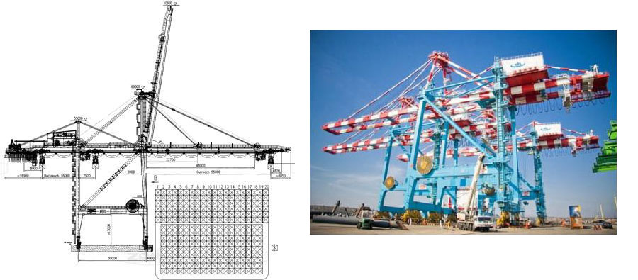
3 ZPMC Quay Cranes were purchased by the owner of the terminal, Trans Invest Service (TIS), Ukraine, in 2006 (fig. 1). Initially, the cranes have been designed for operating either with containers or with heterogeneous cargo [1]. The terminal itself is mostly specialized on coal import and does not have big container flow. Due to this fact, the quay crane has been adopted according the needs of the terminal to work with both containers and coal upon necessity. For this, the terminal engineering department performed a hoppers installation near the crane seaside sill beams and additionally purchased electrical hydraulically driven grabs (fig 2).
initial design of the QC
Figure 1. ZPMC Quay Crane at TIS terminal
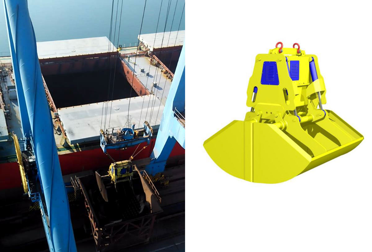
Figure 2. Quay crane modernization for coal unloading
During annual inspections the premature cracks initiation and propagation in the boom and girder structures have been observed. (fig. 3).
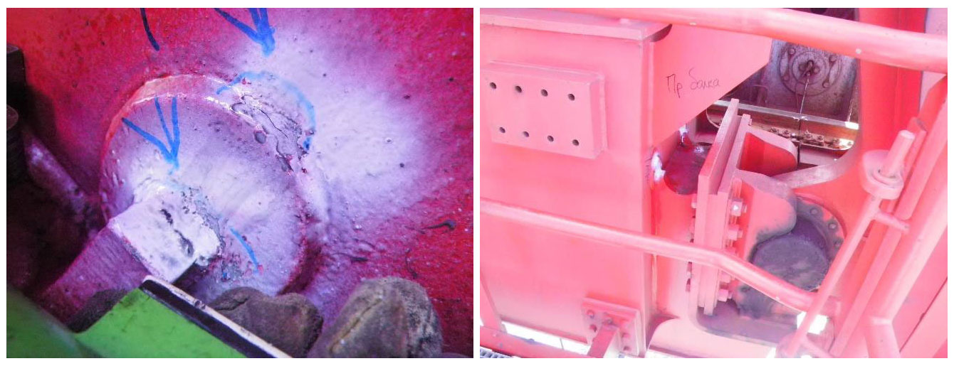
boom/girder connection (saddle pin)
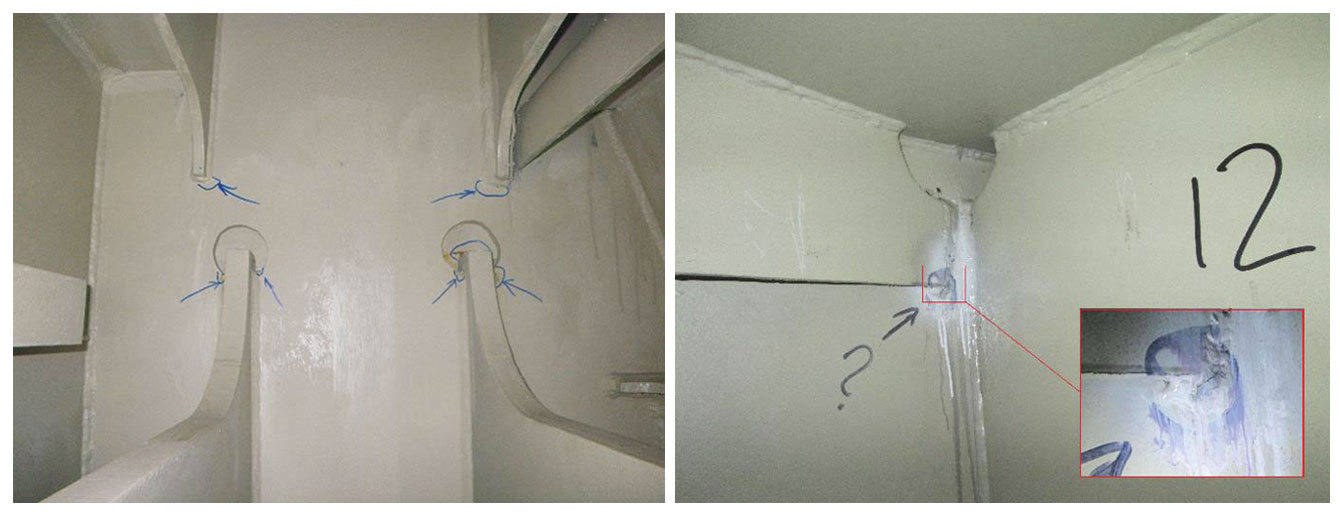
boom and girder inner side
Figure 3. Fatigue cracks examples in the boom and girder structures
We have been asked to find the reason of such premature damage of the structure. As soon as the cranes work with the grab but their structures have not been designed to work with one, the first idea was that the crane operates with overloading due to the grab using. In order to check this assumption the comparison of the stress cycle for operating with spreader and with the grab was needed. The stress cycles have been decided to enquire during the crane operating using stress measurement. For this purpose the 48 channel data acquisition system with strain gauges has been used [2]. The positions of the strain gauges on the crane boom and forestays were as follow (fig. 4).
- one strain gauge per each outer forestay, with their axis along the forestay one, p.1;
- one strain gauge per each inner forestay, with their axis along the forestay one, p.2;
- strain gauge rosette on the boom upper flange (on the boom both beams, between outer and
inner forestays), p.3; - strain gauge rosette on the boom upper flange (on the boom both beams, between
boom/girder joint and inner forestays), p.4.
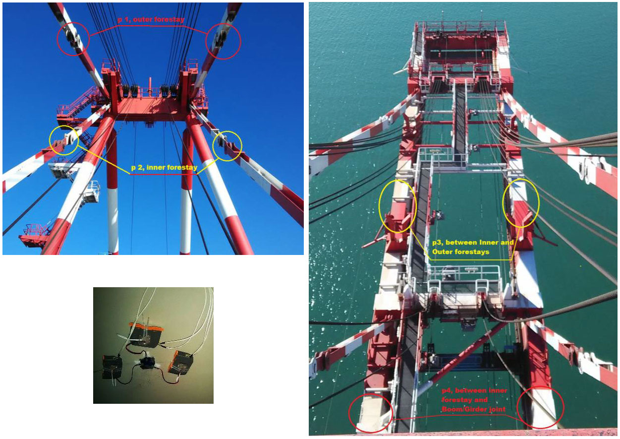
Figure 4. Strain gauges position on the boom and forestays
To help on the test data processing stage to orient better in the stress diagrams 8 sensors of the position have been used to show the trolley location along girder and boom(fig. 5). The signal from each sensor changed its status when the trolley passed it.
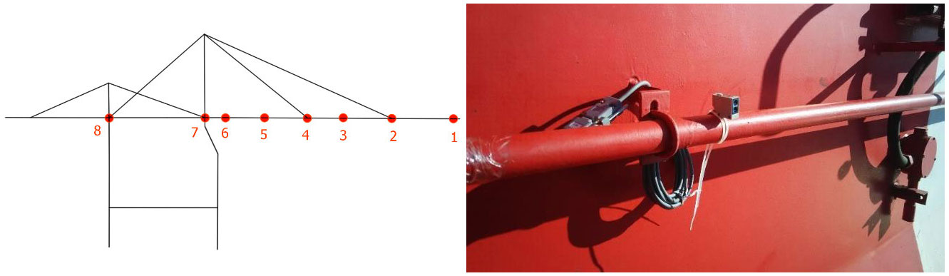
Figure 5. Trolley position sensors installation points on girder and boom
In order to compare the stress cycles for the crane operating with spreader and grab the fatigue damage approach has been used. On the first stage, the stress data has been processed to extract stress cycles from the loading history.
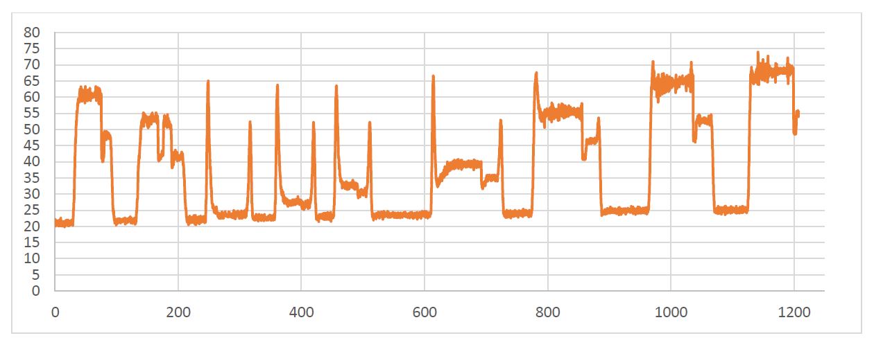
container loading (11 cycles)

container unloading (17 cycles)
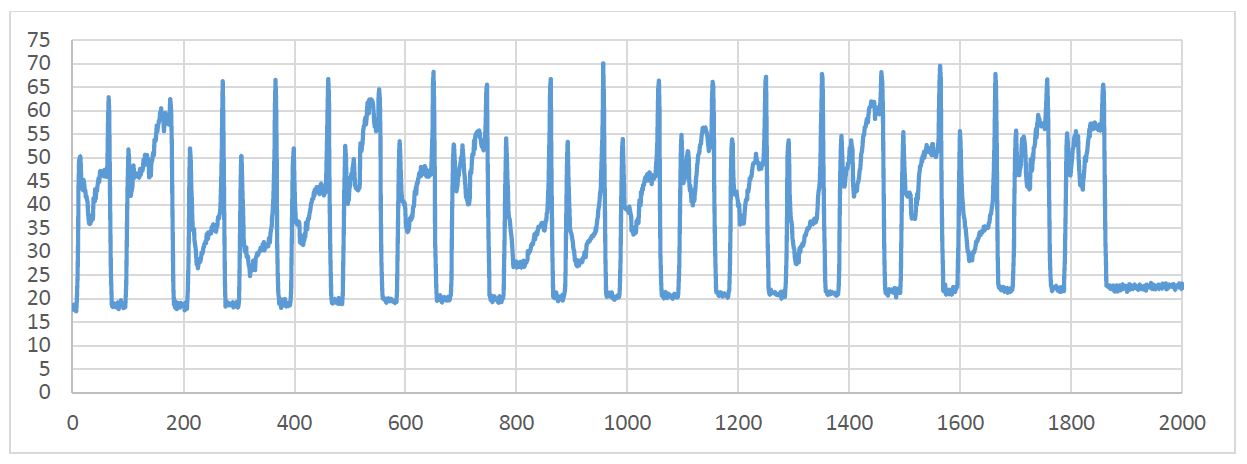
coal unloading using grab (19 cycles)
Figure 6. Stress cycles for p. 4 of the boom left beam during crane operating. The stress cycles for the right beam of the boom have the same shape and are in +/- 1 MPa band.
The rainflow method of the stress cycles counting [3] has been applied to the stress cycles (fig. 6). It reduces the time history to a fatigue cycles (table 1).
Table 1. Rainflow process results
| Cycle Number | Stress Range, MPa | ||
| Container Loading | Container Unloading | Coal Unloading | |
| 1 | 42, 9 | 45, 11 | 45, 14 |
| 2 | 34, 15 | 47, 18 | 45, 10 |
| 3 | 41, 43 | 47, 22 | 48, 26 |
| 4 | 41, 25 | 47, 11 | 49, 25 |
| 5 | 40, 34 | 42, 18 | 48, 20 |
| 6 | 45, 22 | 44, 21 | 46, 12 |
| 7 | 44, 9 | 44, 13 | 48, 20 |
| 8 | 48, 9 | 45, 18 | 46, 10 |
| 9 | 49, 7 | 45, 24 | 47, 28 |
| 10 | - | 47, 0 | 51, 27 |
| 11 | - | 31, 46 | 46, 20 |
| 12 | - | 42, 20 | 45, 15 |
| 13 | - | 32, 22 | 47, 18 |
| 14 | - | 32, 19 | 47, 26 |
| 15 | - | 32, 15 | 47, 14 |
| 16 | - | 43, 14 | 49, 19 |
| 17 | - | 45, 23 | 46, 28 |
| 18 | - | - | 45, 13 |
| 19 | - | - | 44, 9, 13 |
For the fatigue damage accumulation the butt-weld joint of the boom structure has been considered, which corresponds to FAT 71 [4]. The S-N curve is shown in fig. 7. The stress range – number of cycles relation, used here, is:
σm × N = C
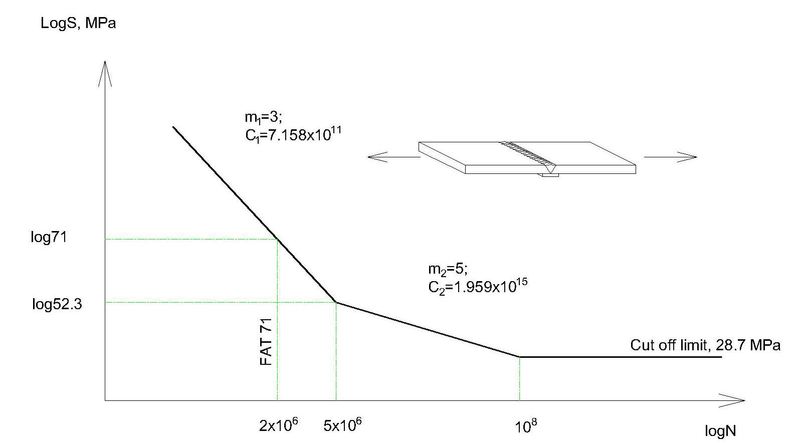
Figure 7. S-N curve for FAT 71
For the fatigue damage calculation the Palmgren-Miner rule has been used as follow
D =n÷N;
According to the recommendations [4] the element failure occurs when D reaches value of 0.5. The result of measured data processing is shown in table 2.
Table 2. Data proceeding result
| Container Loading | Container Unloading | Coal Unloading | |
| Number of crane cycles | 10 | 18 | 14 |
| Accumulated fatigue damage per the crane working cycle | 7.69 ∙ 10-8 | 7.78 ∙ 10-8 | 1.14 ∙ 10-7 |
| The joint residual life, Based on the average accumulated fatigue damage, cycles | 6.5 ∙ 106 | 6.42 ∙ 106 | 4.37 ∙ 106 |
Having analyzed the table. 2 it could be said that using the crane unloading coal with grab decreases the crane life, considered on the design stage.
In order to check the hypothesis that the two distributions of stress ranges (first is for container unloading and the other is for coal unloading, table 1.) belongs to the entire assembly, Kolmogorov and Smirnov test has been used [5]. In this method, D statistic is calculated and the decision about rejecting/accepting of the null hypothesis is made based on comparison of D with its critical value.
Table 3. Data calculation for K-S test
| Fatigue damage per cycle |
Cumulative relative frequency
|
||||||
| Frequency | Cumulative Frequency
|
W=i/n | |W1-W2!| | ||||
| Container | Grab | W1 | W2 | ||||
| 1.71E-08 | 3 | 0 | 3 | 0 | 0.176470588 | 0 | 0.176471 |
| 6.67E-08 | 2 | 0 | 5 | 0 | 0.294117647 | 0 | 0.294118 |
| 7.50E-08 | 1 | 0 | 6 | 0 | 0.352941176 | 0 | 0.352941 |
| 8.42E-08 | 2 | 1 | 8 | 1 | 0.470588235 | 0.052631579 | 0.417957 |
| 9.42E-08 | 4 | 4 | 12 | 5 | 0.705882353 | 0.263157895 | 0.442724 |
| 1.05E-07 | 0 | 4 | 12 | 9 | 0.705882353 | 0.473684211 | 0.232198 |
| 1.17E-07 | 4 | 4 | 16 | 13 | 0.941176471 | 0.684210526 | 0.256966 |
| 1.20E-07 | 1 | 0 | 17 | 13 | 1 | 0.684210526 | 0.315789 |
| 1.30E-07 | 0 | 3 | 17 | 16 | 1 | 0.842105263 | 0.157895 |
| 1.44E-07 | 0 | 2 | 17 | 18 | 1 | 0.947368421 | 0.052632 |
| 1.76E-07 | 0 | 1 | 17 | 19 | 1 | 1 | 0 |
| D = 0.442724 | |||||||
The statistic critical value for 5% significance level is ?0.05 = 0.454035.
As soon as the calculated value of D=0.442724 is less, then the critical one of ?0.05 = 0.454035, the null hypothesis is not rejected.
Due to the fact that the calculated value of the statistic D is very close to its critical limit the Wilcoxon Mann Whitney test is used to check the obtained result. The calculated value of modified statistic, which uses in this test, is Z=0.013844. The critical value is ?0.05 = 1.96 and the null hypothesis is not rejected.
This means that with 95% probability the two fatigue damage distributions, accumulated during operating with spreader and with the grab, belong to one fatigue damage distribution. In the other words, the operating of the crane with the grab does not change the crane appliance group and could not be the reason of the premature crack initiation in the crane structure.
The second possible reason that has been checked was the force distribution in the boom inner and outer forestays. The information from the strain gauges has been converted to the force in the forestays (fig. 8).

Figure 8. The force in forestays during the lowering down the boom
It could be seen that at the boom working (horizontal) position the right side inner forestay is overloaded for 50% and right side outer forestay – for 56%. It creates the significant overloading of the boom right beam. Due to the big safety factors, which have been used on the stage design, mentioned above boom right beam overloading is not enough to initiate the boom plastic deformation [6] of the boom, but leads to high level of the mean component of the stress history, which decreases the boom
structure fatigue life.
So, in order to increase the residual life of the crane boom and girder structures it is recommended to set up the force distribution in the boom inner and outer forestays properly. It could be done by rotating eccentric pins in forestays with concurrent strain gauge measurements of the forces distribution for controlling the set up result.
Conclusion
- After analyzing the stress fluctuation in the crane boom structure critical points it could be seen that the operating of the crane with the grab does not change the crane appliance group and could not be the reason of the premature crack initiation in the crane structure.
- The checking the force distribution in the boom forestays shows that the right side forestays are significantly overloaded which leads to the high level of mean stress and in the result affects the fatigue life of the boom right beam structure.
- Thus, the reason of the premature crack initiation and propagation could in the crane operating without forestay force distribution proper setup that should have been completed after cranes have been transported by sea.
Reference
- Cranes – Design, Practice, and Maintenance. Ing. J. Verschoof. Professional Engineering Publishing.2nd Edition. 2002. – 329p.
- Modern Experimental Stress Analysis. James F.Doyle,Willey,2004.-424 p.
- ASTM E 1049-85 Standard Practice for Cycle Counting in Fatigue Analysis.
- Fatigue design of welded joints and components. XIII-1539-96/XV-845-96. A. Hobbacher. Abington Publishing.1996. – 127p.
- Stepnov M. N. Statistical methods of mechanical tests proceeding (in Russian) Степнов М. Н. Статистические методы обработки результатов механических испытаний: Справочник. – М.:Машиностроение.1985. – 232с., ил.
- Konoplev A., Starykov M., Gubskii S and others. Upon the question of necessity of Quay crane forestays force distribution adjustment after their mounting and during exploitation period.
