

Approach for Measuring a Ship to Shore Crane Actual Wheel Load
Knowing the real crane deadweight, center of gravity (COG) and wheel loads instead of nominal ones is crucial for many reasons. One of the reasons relates to the checking the quay strength where the crane is going to be installed and it should be based on the crane maximum real wheel loads. Another example could be the crane transportation by sea on the deck of the vessel (Starykov & Van Hoorn, 2017). In this case predicting the precise value of the crane deadweight and its COG plays a key role in accurate calculation of the vessel stability, acceleration calculation from the ship motions and the vessel’s deck strength. This paper demonstrates a new approach to finding the crane wheel load and in the result the deadweight and COG position. This method does not need special arrangement and uses combination of strain gauge measurements and Finite Element (FE) analysis only. The application of the method is demonstrated on example of the ship loader for which the possibility of capacity increase has been assessed.
INTRODUCTION
One of the main limitations to the crane design is the maximum allowable wheel load, which mainly comes from a quay structure strength. Usually, this parameter is obtained from the crane FE model. The main source of mismatching with reality is that the model provides the nominal wheel loads, i.e., corresponding to the nominal dimensions and nominal weights of the structure elements. But in reality, the tolerances for weight and dimensions introduce the difference in position of COG and crane dead weight. As the wheel load is a crucial characteristic it should be controlled more precisely. If the crane was a smaller structure it would be possible to weigh it directly using a special platform or using a heavy lift to determine the real COG position and weight. For the contemporary quay cranes, which weight comes up to 1500 tones (Bartošek & Marek, 2013), using direct weighing would be a challenging task. Another area where the value of the crane deadweight and COG could be used are for the crane sea transportation. In this case knowing the dead weight and COG is critical for the ship stability and vessel acceleration calculation.
APPROACH DESCRIPTION
This work is proposing an approach that allows measuring the crane wheel load magnitude using strain gauges (Tutak, 2014) with further processing with FE analysis (Werkle, 2021). The method could be described as crane ‘weighing’ using the strain gauges. The approach’s main steps are:
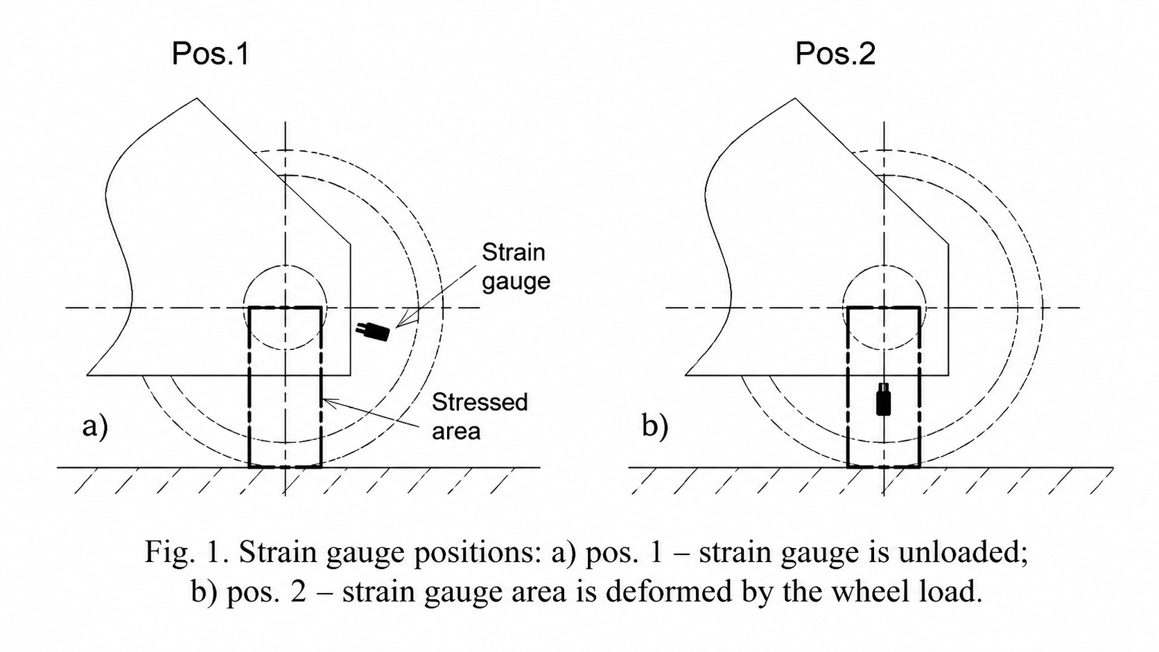
Step 1. The stress in the crane travel wheels appears in the area between the wheel pin/shaft and the contact of the rail with the wheel, see Fig.1 and the rest of the wheel is unloaded. Using this observation, a strain gauge is attached to the crane travel wheel at pos. 1 (Fig. 1. a) to the area with no stress.
Step 2. Start crane moving and as the result of wheel rotation the area with the strain gauge becomes loaded by the wheel load (pos. 2, Fig. 1. b) and during the further rotation the stress there disappears again.
Fig. 1. Strain gauge positions: a) pos. 1 – strain gauge is unloaded;
b) pos. 2 – strain gauge area is deformed by the wheel load
Step 3. The measured signal is proportional to the wheel load magnitude, but in order to find out the load in tons the additional step, calibration, is needed that would allow to transfer the original signal of mV/V to tons. The calibration is crated using calibration beam and the FE analysis of the wheel model
APPLICATION TO THE SHIP LOADER
The described approach is demonstrated for project of ship loader modification, when its capacity had been increased twice from 2000 t/h to 4000 t/h. One of the milestones of this project was to assess the increased magnitude of the wheel load with its further comparison with the maximal allowable load on the quay. This approach could be extended to the different types of cranes, like boom level-luffing cranes, quay cranes (ship-toshore cranes) that have the same travel arrangement, when the crane moves along the rails laying along the quay. Due to the lack of data on the ship loader structure element weights and its total COG the proposing experimental approach utilizing strain gauge measurement has been developed.
Fig. 2. Top view of ship loader and its travel arrangement
The ship loader has four supports: two sea side (labeled A and B) and two land side (labeled C and D), see Fig. 2. Each sea support has 4 wheels, and each land support has 3 wheels, see Fig. 3. The strain gauges have been attached to the outmost wheels of each support.
Ship loader and its travel arrangement
Ship loader and its travel arrangement — sea side support
Ship loader and its travel arrangement — land side support
Step 1. Strain gauges are attached to the wheels in the “unloaded” area, away from area with stress from wheel / rail contact, see Fig. 4.
Fig. 4. Strain gauge attachment to wheel, pos. 1.
Step 2. Firstly, the crane is put into position for which the wheel load is measured. In case of ship load