In the paper in terms of repairing of RTG the necessity of using a state-of-the-art CAD and CAE programs by companies which are engaged in crane repairing and modernization business is shown.
Key words: RTG crane, crane metal construction repair, cargo lifting machines.
Methods of problems solution, which should be done during normal engineering practice, are not always similar. Especially when the repairing or modernization of cargo lifting and conveying machines is done, with involving its basic features changing, like speed, safe working load (SWL), outreach etc.
Even the using of a common repairing method is not always able due to different bounding conditions. That is why the necessity of appropriate solution idea for every certain problem arises. For the transition from an idea, which result is just a sketch of future changes in the crane, to drawings creation it is needed to determine the necessity of existing crane metal construction joints reinforcement, fulfill their strength assessment or changes in the metal construction, perform verification for the whole reconstructed machine (strength, stability, fatigue etc.). On the next stage the resulting information, obtained after strength assessment (joints that are needed to be reinforced, types of reinforcements, thickness of metal sheets etc.), is passed for the drawing creation. And based on the drawings the whole work is done.
Thus, described above succession is basic set of actions for repairing works or modernization. And the company, which performs this works, must have highly qualified specialists with not only a significant experience, but strong knowledge of strength calculation, designing and site work execution. However many people disparage the up-to-date computing programs and prefer them simple hand calculation, based on strength of material. Nevertheless they usually forget that the main task for an engineer is not just getting a result using programs or hand calculation, based on simplified theories, but analyze the derived result, assess the error ability in the calculation, compare with the results for the similar objects received in previous projects.
As an example for application mentioned above work succession the repair of the RTG crane in PSA (Singapore) is shown. This crane is used for yard operations at container terminals. The work was fulfilled by PORTEK System & Equipment Pte Ltd – the leading company in the port business.
During accident-free exploitation of such cranes owners are usually faced with the similar problems: span increasing due to the deformations of main girders and legs and main girders maximal deflection changing. According to norms of crane exploitation the maximal deflection does not have to be bigger than a certain value that is proportional to the crane span. The span tolerance is shown in the crane drawings.
According to the RTG survey measurement before commencement of repairing work maximal deflection of main girder was 28 mm with trolley in the middle of the main girder without container. At the same time maximal permissible deflection have not be more then 32 mm for the trolley in the middle of the girder with a testing weight. Span increasing was 280 mm.
Due to a repairing procedure the RTG crane (fig. 1) was lifted up for 0.5 meters above ground level (fig. 2) and put onto the lattice repairing tower (fig. 3) that was mounted from below of it. Main lattice elements, pillars, are made from tubes.
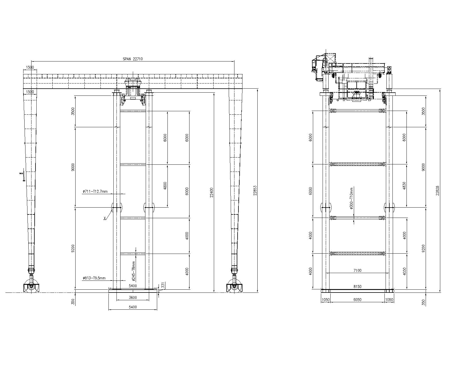
Figure 1. The main view of the RTG crane, mounted on the repairing tower
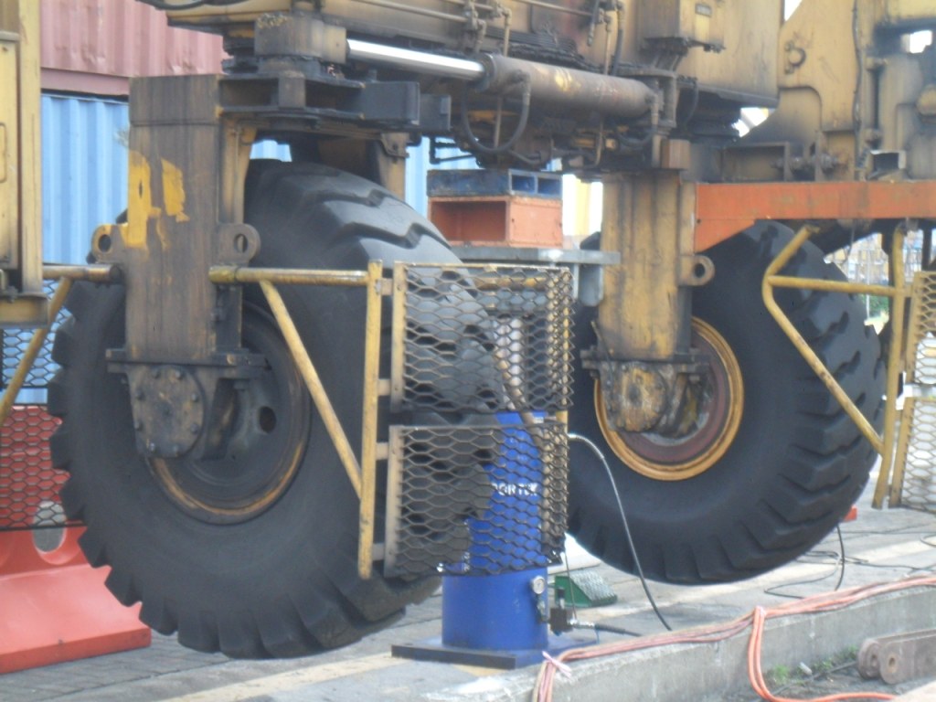
Figure 2. The RTG crane lifting for mounting the repairing tower below it
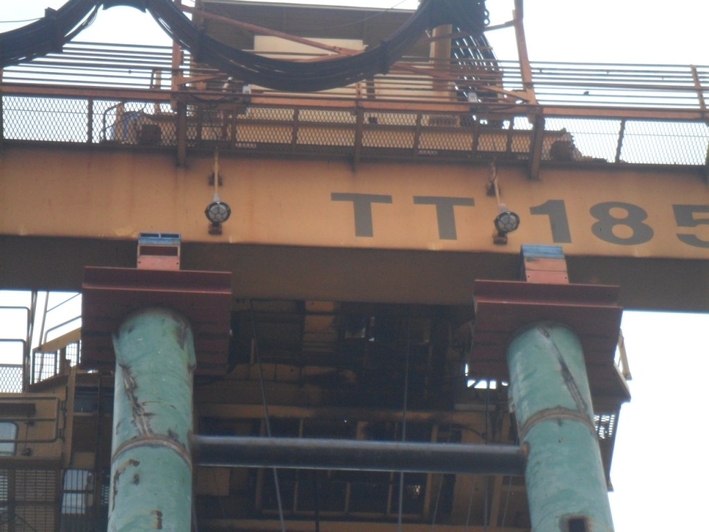
Figure 3. The RTG crane main girder resting on the top of the repairing tower
Before the work commencement the finite element analysis of the repairing tower was performed. The calculation was done to assess tower strength, stability as a lump construction and its pillars buckling. During calculation the tower was undergone to the vertical forces of the RTG weight and horizontal wind forces to the RTG and the tower. Also the unsymmetrical load on tower pillars was considered (fig. 4).
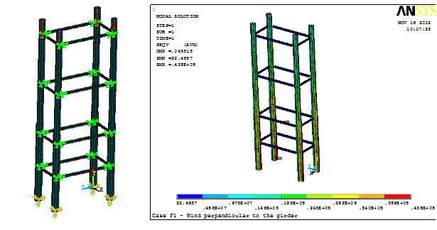
Figure 4. Boundary conditions and calculation results (equivalent Misses stresses) for repairing tower
For main girder deflection improving it was decided to use its heating, which is the typical method for similar cases. But the customer refused this method to be applied. The reason is possible girder deformation not only in a vertical, but also a horizontal plain. As a result it was resolved to use plastic deformation of the main girder during pulling the RTG crane legs together for its deflection improving. Calculation was done for determination of the minimal forces, which should be applied to the RTG legs, to put material in the middle of the main girder to plastic state (fig. 5 and fig. 6). After main girder deflection decreasing the main girder was reinforced by additional plates that were welded to both its sides.
Figure 5. Boundary conditions for the RTG crane, which is situated on the repairing tower
Figure 6. Von Misses equivalent stresses for the RTG crane on the repairing tower with horizontal forces applied to legs
For easier and more precise crane span restoration, in the joints of legs with main girder the separation of three leg plates from girder was performed (fig. 7) for each joint of leg-girder connection. Leg pulling was done by horizontally disposed jacks.
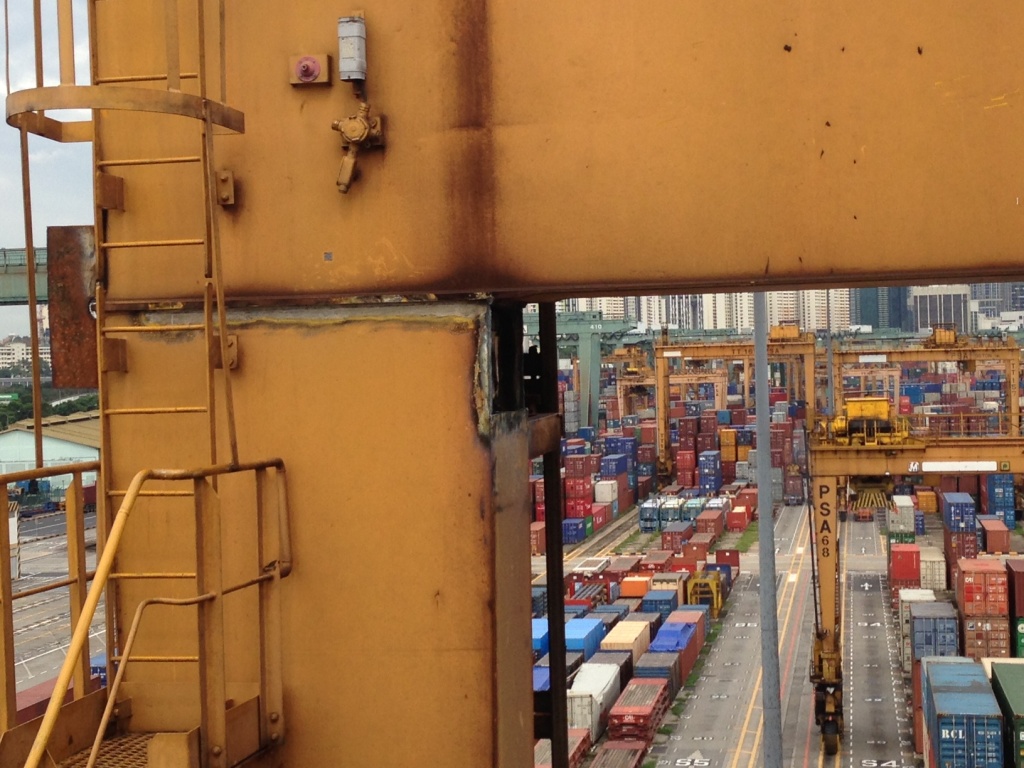
Figure 7. Disconnection of three leg plates from the main girder
After finishing span restoration the leg-girder connection was renewed and additional gusset plates were attached (fig. 8).
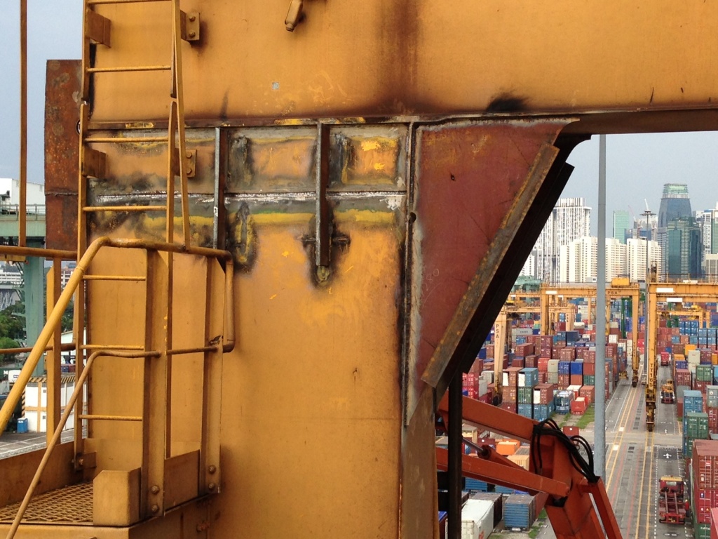
Figure 8. Leg-girder joint reinforcement (before final adjustment and painting)
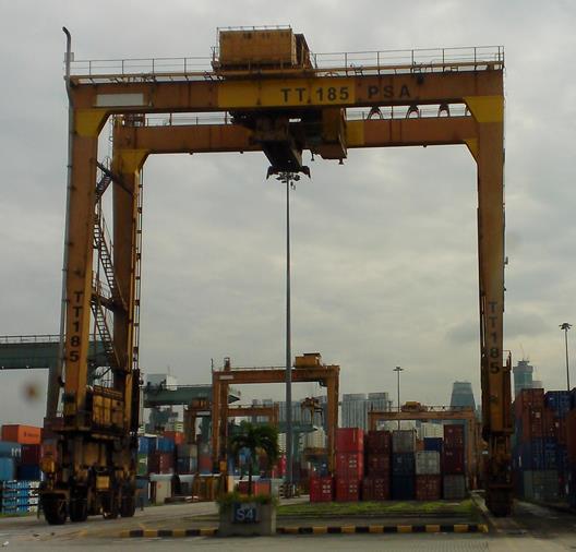
Figure 9. The RTG crane after repair
Below the measurement results after repairing are showed:
- Span increasing was reduced from 280 (before the repairing) to 14 mm (after repairing).
- The biggest deflection of main girder during testing with trolley and test weight of 43 tones is 23 mm (after repair) instead of 28 mm for trolley without testing weight (before repair).
Conclusion
Using state-of-the-art programs for calculation and design in crane business is not something unusual any longer, but becomes necessary tool in engineering daily procedure of crane repairing, designing and modernization. It allows with more precision determining the conditions of metal to transfer into plastic state, calculate temperature stress, local stress in element joints, which can not be determined using common approach, based on “Strength of material” hand calculation. Although the common succession for repairing or modernization is still the same: main idea creation – strength analysis – drawings creation – execution phase, but due to the more precise modeling of stress distribution inside joints and thus a better loading process understanding inside them the overall work quality becomes much higher.
